RGB interface definition of parallel transmission mode
Date:2023-09-06
In this article, we discuss one of the interface methods of the industrial
LCD screen -RGB interface of parallel transmission method, and how to generate
line and column drive signals from the RGB interface in parallel
transmission.
RGB interface of parallel transmission method
First of all, Transmitting RGB data in parallel mode, that is, each base
color signal data uses a separate data wire for transmission.Corresponding to
the 8 -bit LCD panel,the three sub -pixels of R, G, and B use 8 -bit
respectively. According to the amount of data, the RGB data is 24 bits, and the
RGB data cable also has a total of 24 pieces. Metaphors to queue, and the
parallel transmission data is to line each base data into a horizontal team and
output together.
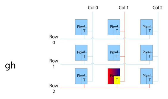
TFT panel work principle
Next, let's talk about the basic working principles of the TFT panel. LCD
display is composed of a series of liquid chip. The crystal itself is not bright
which is organized in a random mode,when there is no electric field. When the
electric field is applied, the crystal is aimed at the electric field. Electric
fields of various intensity are like a "door" that makes the backlight of
different strength pass through the crystal. When the crystal is arranged
vertically on the backlight, the backlight cannot pass through the crystal. From
the perspective of electronic structure, the LCD panel consists of a grid of the
electrical signal. Pixels are treated by a matrix, and each interaction belongs
to a pixel. Each pixel is connected vertically with rows and columns through a
transistor. When the lines and columns are selected by the integrated circuit
controller, the pixels under the interaction of the row and column are enabled
or disabled.
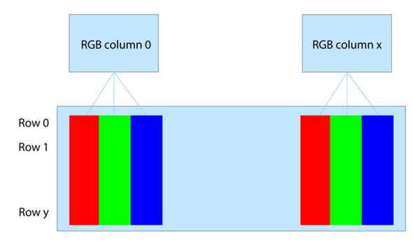
A pixel generates a specific color
In order to make a pixel produce a specific color, one pixel consists of 3
sections. They are used through red, green, and blue filter to form an RGB
pixel. For a 320*240 RGB TFT display, there is actually 960 (320X3) columns and
240 lines.
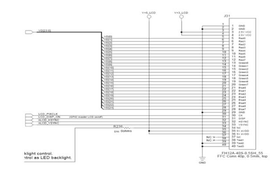
Most LCDs have an RGB interface with parallel transmission method, which is
located between the graphic controller as the signal source and the input of the
display module.The RGB interface is responsible for sending image data
information (gray level and color) in real time. Image data transmits through
the TTL voltage level to "0" or "1" in a digital manner. For the RGB interface,
each signal has a corresponding line. Below is a signal connection of the RGB
interface of each pixel 24bits.
Vertical synchronization vsync sets the beginning of a new frame. There is
no image data during the VSYNC synchronization pulse, and these data are marked
as VBP and VFP. The same principle is also applicable to HSYNC synchronous
pulse, using HBP and HFP marks. HSYNC pulse is responsible for a new line.
Between the two HSYNC pulses, the gray -level RGB color data of a line (line)
must be transmitted. Since the TFT display can drive 3 segments (1 pixel) per
clock, the length of the LCD CLK is determined by the number of resolution
columns. For example, the resolution of a TFT display is 480*272. We assume the
following parameters:
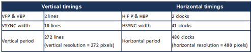
So according to the above parameter table, we can get:
One line needs (2+2+41+480) clocks = 525 clock/line
A full frame requires (2 + 2 + 10 + 272) lines = 286 lines/frame
Number of clocks of a full frame = 286*525 = 150150 clocks/frame
For the clock speed of 7.83MHz, the LCD will be refreshed at a speed of
7.83m/150.15k = 52.1Hz.
AUO LCD:https://www.auo-lcd.com/products/auo-lcd-screen/
INNOLUX LCD:https://www.auo-lcd.com/products/innolux/