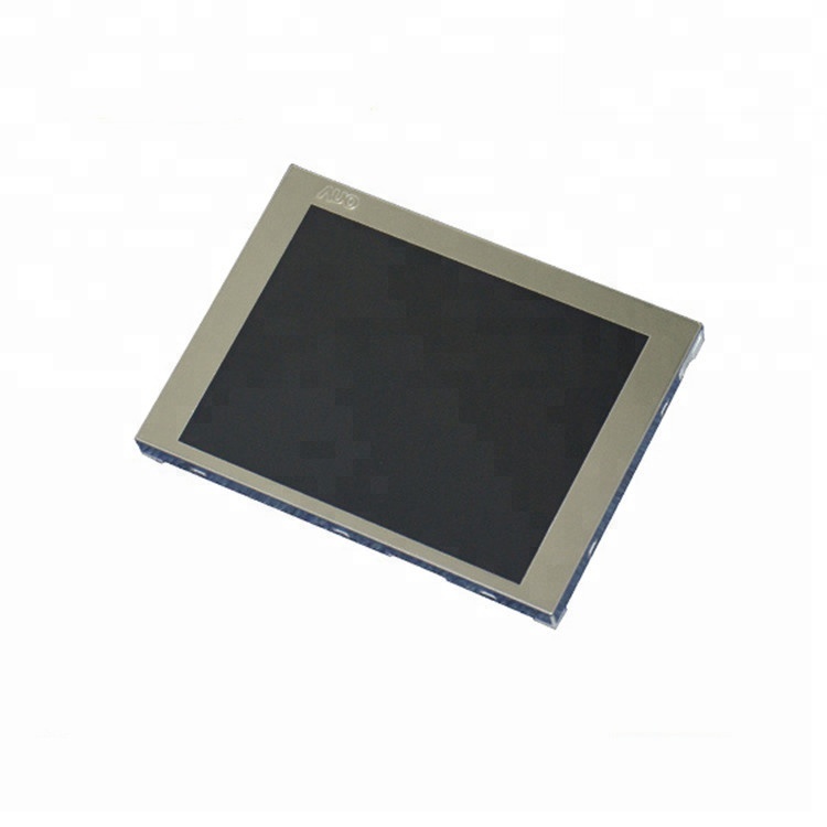
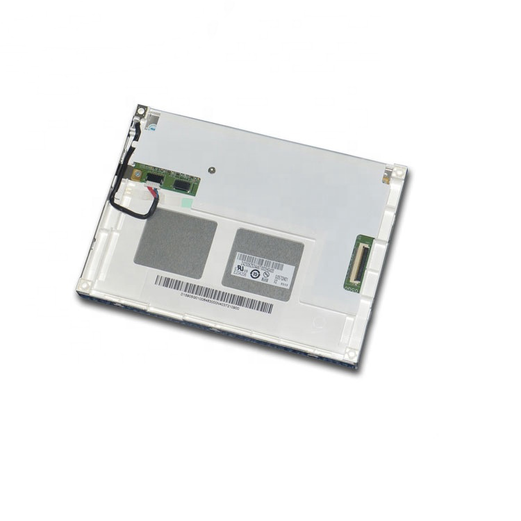
AUO G057QN01 V2 5.7-inch QVGA TFT LCD Specifications
AUO G057QN01 V2 is a 5.7-inch TN TFT-LCD module with 320 × 240 QVGA resolution, 262K colors and a CMOS 6-bit parallel RGB interface. It provides 800 cd/m² typical center luminance, a 33-pin LCD signal connector and an LED backlight unit with an integrated driver circuit. The module is designed for industrial display applications.
Specification basis: AUO G057QN01 V2 Final Specification supplied for this page. Its revision record lists Version 1.2 dated 11 December 2014; the printed page footers retain “Ver. 1.0”. References below use the PDF page positions, 1–24. Minimum, typical and maximum values retain their original meanings.
Display and mechanical specifications
Display, dimensions and interface| Parameter | Specification | PDF page |
|---|
| Model / manufacturer | G057QN01 V2 / AU Optronics (AUO) | 1, 5 |
| Screen size / resolution | 5.7 inches; 320 × 240 pixels, QVGA; 320 × 3 (RGB) × 240 subpixels | 5 |
| Display mode / colors | TN, normally white; 262K colors; RGB vertical stripe | 5 |
| Signal interface | CMOS 6-bit parallel RGB: 6 bits per color channel, 18 data bits in total | 5, 14, 18 |
| Active area / pixel pitch | 115.2 × 86.4 mm (H × V); 0.36 × 0.36 mm pixel pitch | 5 |
| Module dimensions | 144.0 × 104.6 × 12.3 mm typical (H × V × D); drawing specifies 12.8 mm maximum depth | 5, 22 |
| Weight | 150 g typical; 165 g maximum | 5 |
| Surface treatment | Anti-glare; 3H surface hardness | 5 |
| Preferred viewing direction | 12 o'clock | 5 |
| Backlight construction | LED backlight unit with LED driver circuit included | 5 |
Use the mechanical drawing on PDF page 22 to verify mounting positions, connector locations and dimensional tolerances before design approval. Dimensions alone do not establish replacement compatibility.
Optical performance
Unless a row states otherwise, optical characteristics below are measured under stable conditions at 25 °C. L/R/U/D means left, right, up and down; CR is contrast ratio.
Luminance, contrast and viewing angles| Parameter | Specification | PDF page |
|---|
| Center white luminance | 600 cd/m² minimum; 800 cd/m² typical, at VLED = 12 V and PWM duty = 100% | 6 |
| Contrast ratio | 500:1 minimum; 800:1 typical | 6 |
| Viewing angle, L/R/U/D | 80°/80°/70°/70° typical; 70°/70°/60°/60° minimum, at CR = 10 | 6 |
| Response time, rising / falling | 15 / 10 ms typical; 20 / 15 ms maximum | 6 |
| Response time, total | 25 ms typical; 35 ms maximum, rising + falling | 6 |
| Five-point luminance uniformity | 1.3 maximum ratio of the brightest point to the dimmest point; this is a ratio, not a percentage | 6–7 |
| White chromaticity, CIE 1931 | x = 0.313, y = 0.329 typical | 6 |
Power, backlight and environmental limits
The LED electrical and operating-life figures below come from the parameter table specified under stable conditions at 25 °C. Its estimated life rating does not apply unconditionally across the full environmental range. Follow the individual test conditions and notes when reviewing a design.
Electrical operating characteristics and backlight| Parameter | Specification | PDF page |
|---|
| LCD logic supply, VDD | 3.0 V minimum; 3.3 V typical; 3.6 V maximum | 10 |
| LCD power, PDD | 0.46 W typical; 0.51 W maximum, all-black pattern, VDD = 3.3 V, 60 Hz | 10 |
| Backlight driver supply, VLED | 9 V minimum; 12 V typical; 20 V maximum operating input | 11 |
| Backlight input current | 0.24 A typical; 0.29 A maximum, at VLED = 12 V, PWM duty = 100% | 11 |
| Backlight driver input power | 2.88 W typical; 3.48 W maximum, at VLED = 12 V, PWM duty = 100% | 11 |
| Total module power, summary value | 3.34 W typical: LCD 0.46 W + backlight 2.88 W, all-black pattern, full load, VLED = 12 V | 5 |
| PWM dimming | 200 Hz to 30 kHz; 1% to 100% duty cycle | 11 |
| PWM logic levels | High: 2.0–5.5 V, 3.3 V typical; low: 0.2 V maximum | 11 |
| Backlight enable levels | On: 2.0–5.5 V, 3.3 V typical; off: 0.8 V maximum | 11 |
| Backlight operating life | 50,000 hours minimum, estimated to 50% of initial brightness; LED parameter table basis: stable 25 °C. Higher current, ambient temperature or humidity reduces life | 11, notes 5–6 |
Use the operating supply ranges above for design. The separate absolute-maximum ratings on PDF page 9 are stress limits, not recommended operating voltages. In particular, the 23 V backlight absolute maximum is not the 20 V maximum operating input. The backlight-life estimate is not a warranty for the complete equipment.
Temperature and humidity ratings| Parameter | Specification | PDF page |
|---|
| Operating temperature | −30 to +85 °C; operation only is guaranteed across this range; optical performance is evaluated at 25 °C | 5, 9 |
| Storage temperature | −30 to +85 °C, non-operating | 5, 9 |
| Operating / storage humidity | 5%–95% RH, non-condensing; maximum wet-bulb temperature 39 °C | 9 |
Connectors and RGB signal pinout
Connector references| Parameter | Specification | PDF page |
|---|
| CN1: LCD signal connector | 33-pin Starconn 089H33-000100-G2-R. The specification also names IMSA-9637S-33Y902 and ELCO 08-6210--033-340-800+ as compatible connector references. | 18 |
| CN2: backlight driver input | 6-pin JST SM06B-SRKS-G-TB; compatible reference JST SM06B-SRSS-TB (LS) (SN). Mating connector: JST SHR-06V-BKHF-B or compatible. | 18 |
| CN3: LED light-bar connection | 6-pin light-bar connector, distinct from CN2. The LED forward-voltage figures belong to the LED side, not the external backlight-driver supply. | 11, 19 |
CN1 signal assignment (PDF page 18)| CN1 pin(s) | Signal |
|---|
| 1, 5, 12, 19, 26, 33 | GND |
| 2 | DOTCLK |
| 3, 4, 32 | NC |
| 6–11 | R0–R5 |
| 13–18 | G0–G5 |
| 20–25 | B0–B5 |
| 27 | DE |
| 28, 29 | VDD |
| 30 | R/L |
| 31 | U/D |
CN2 pins 1–2 are VLED, pins 3–4 are GND, pin 5 is PWM DIM and pin 6 is LED ON/OFF. Confirm pin-1 orientation using the original drawings. Turn power off before connecting or disconnecting cables; follow the power and enable sequence in the specification, pages 11 and 17. PWM must not be left floating.
RGB timing overview| Parameter | Specification | PDF page |
|---|
| Input timing mode | DE mode only | 16 |
| Dot clock | 6.2 MHz minimum; 6.4 MHz typical; 12.1 MHz maximum | 16 |
| Recommended frame rate | 60 Hz | 16 |
| Typical total / active horizontal timing | 408 / 320 clock cycles | 16 |
| Typical total / active vertical timing | 263 / 240 lines | 16 |
Selection and integration checklist
- Match the full G057QN01 V2 label and applicable specification to the module being supplied.
- Check the host RGB voltage, DE-mode timing and 33-pin cable assignment; check backlight power and PWM/enable separately.
- Verify mounting, enclosure clearance, preferred viewing direction and the equipment’s operating environment.
- Evaluate readability and thermal conditions in the actual installation. The panel specification does not certify a complete weatherproof assembly.
- For purchasing or replacement review, provide the original panel label, connector and cable photos, equipment model, required quantity and application conditions.
G057QN01 V2 FAQ
What is the AUO G057QN01 V2?
G057QN01 V2 is a 5.7-inch AUO TN TFT-LCD module for industrial display designs. It has 320 × 240 QVGA pixels, 262K colors and 800 cd/m² typical center luminance. Its signal input is CMOS parallel RGB.
Is the interface LVDS or parallel RGB?
The specified interface is CMOS 6-bit parallel RGB, with 6 data bits per color channel and 18 RGB data bits in total. CN1 is a 33-pin connector. It is not a direct LVDS, HDMI or MIPI-DSI input; a host or controller must match its RGB signals and timing.
What supply voltages does G057QN01 V2 require?
The LCD logic supply VDD is 3.3 V typical, with a 3.0–3.6 V operating range. The backlight driver input VLED is 12 V typical, with a 9–20 V operating range. The LED-side forward-voltage figures are not the voltage to apply to CN2.
Is 800 cd/m² the minimum brightness?
No. The specification lists 800 cd/m² as typical and 600 cd/m² as minimum center white luminance. These optical values are measured under stable conditions at 25 °C, with VLED = 12 V and PWM duty cycle = 100%.
What are the viewing angles and preferred viewing direction?
Typical left/right/up/down viewing angles are 80°/80°/70°/70° at CR = 10. The minimum values are 70°/70°/60°/60°. The specified preferred viewing direction is 12 o'clock.
What is the operating temperature range?
The specified operating and storage ranges are both −30 to +85 °C. The environmental-rating note guarantees operation only; optical performance is evaluated at 25 °C. Observe the non-condensing humidity and maximum wet-bulb limits.
Does the 50,000-hour backlight figure guarantee ten years of service?
No. In the LED parameter table, specified under stable conditions at 25 °C, the specification places 50,000 hours in the minimum column. Operating life means the estimated time until brightness falls to 50% of its initial level. It is not a calendar-life or complete-product warranty, or a guarantee across the entire operating-temperature range. Higher current, temperature and humidity can shorten backlight life.
Does high brightness mean the module is weatherproof or IP65 rated?
The supplied specification does not establish an IP65 ingress-protection rating for this module. Evaluate ambient-light readability, enclosure sealing, thermal design and condensation protection for the complete equipment; brightness alone does not establish outdoor suitability.
Can I replace another 5.7-inch LCD with G057QN01 V2?
Screen size alone does not establish compatibility. Compare the complete model and revision, RGB timing, signal voltage, CN1 pinout, CN2 power and control, mounting positions, dimensions and viewing direction against the original equipment documentation. Request a technical review before selecting a replacement.
Request the specification and a technical review
Contact Hangzhou Xuhong Technology Co., Ltd. with the complete G057QN01 V2 model and your requirements to request the applicable specification, a cable and interface review, or a quotation. Confirm the offered module revision, current availability, commercial terms and delivery before ordering.
Request G057QN01 V2 technical review / quote
Email: market@hzxuhong.com