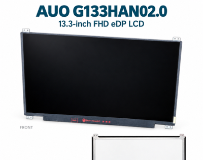
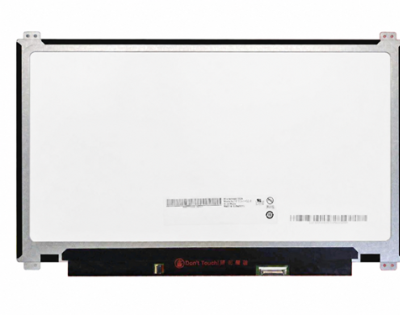
AUO G133HAN02.0 13.3-inch FHD eDP LCD Specifications
AUO G133HAN02.0 is a 13.3-inch-class, normally-black TFT-LCD module for industrial display applications. It combines 1920 × 1080 FHD resolution, 16.2M colors and a 2-lane eDP 1.2 interface with an anti-glare surface and 400 cd/m² typical center luminance. The module includes an LED backlight-driving circuit and uses separate LCD-logic and backlight supplies.
Specification basis: AUO G133HAN02.0 Final Specification. The revision record includes version 1.2; the cover is approved/prepared on 25 February 2020. A separate date is not printed for the 1.2 entry. This supplied PDF has 33 pages. Page references below follow the supplied PDF page numbers, which agree with the printed page positions. This page covers only the complete G133HAN02.0 model; do not treat another suffix as the same specification.
Display and mechanical specifications
Model identity, size and construction| Parameter | Specification | Source page |
|---|
| Full model / manufacturer | G133HAN02.0 / AU Optronics (AUO) | 1 |
| Display size / format | 13.3-inch class (13.26-inch designation); 336.71 mm diagonal; 1920 × 1080 FHD, 16:9 | 6 |
| Pixel arrangement / pitch | RGB vertical stripe; 1920 × 3 (RGB) × 1080 subpixels; 0.1529 × 0.1529 mm pixel pitch | 6 |
| Active area | 293.472 × 165.078 mm | 6 |
| Display mode / color support | Normally black; 16.2M colors as specified | 6–7 |
| Signal interface | 2-lane eDP 1.2 | 6 |
| Surface treatment | Anti-glare | 7 |
| Outline including brackets | 306.3 mm typical width (305.8–306.8); 195.3 mm typical height (194.8–195.8) | 6 |
| Maximum thickness | 3.0 mm at panel side; 3.2 mm at PCBA side | 6 |
| Weight | 280 g maximum | 6 |
| Backlight construction | LED backlight with driving circuit | 1, 6 |
Dimensions and weight retain their typical/maximum labels. Verify the applicable mechanical drawing, brackets, mounting positions and cable orientation against the actual module before approving a mechanical replacement.
Optical characteristics
Detailed optical values are measured at stable 25 °C. L/R/U/D means left, right, up and down, and CR means contrast ratio.
Luminance, viewing angles and optical performance| Parameter | Specification | Source page |
|---|
| Center white luminance | 320 cd/m² minimum; 400 cd/m² typical, detailed optical table: ILED = 20 mA, base panel only | 8 |
| Contrast ratio | 600:1 minimum; 800:1 typical | 8 |
| Viewing angle, L/R/U/D | 89°/89°/89°/89° typical; 80°/80°/80°/80° minimum, at CR = 10 | 8 |
| Response time, rising + falling | 27 ms typical; 35 ms maximum is stated in the general-specification summary | 6, 8 |
| Luminance uniformity | 1.25 maximum at 5 points; 1.6 maximum at 13 points; brightest-to-dimmest luminance ratios | 8 |
| NTSC color gamut | 45% typical | 8 |
| White chromaticity, CIE 1931 | x = 0.313, y = 0.329 typical | 8 |
Measurement-current note: the general luminance summary uses ILED = 24 mA, while the detailed optical table identifies ILED = 20 mA for the base panel. These different labels are retained by section; do not assume either value is the external backlight-input current or a guarantee for a completed cover-glass assembly.
LCD logic and integrated backlight driver
The logic-power table is measured at 25 °C and 60 Hz. The LED-characteristic table also uses Ta = 25 °C; observe the stated test patterns, connector reference points and calculation notes.
Operating supplies, power and LED lifetime| Parameter | Specification | Source page |
|---|
| LCD logic supply, VDD | 3.0 V minimum; 3.3 V typical; 3.6 V maximum | 15 |
| Logic power, PDD | 0.7 W typical; 0.8 W maximum; maximum-measurement condition: white pattern, VDD = 3.3 V | 15 |
| Logic current, IDD | 231 mA typical; 242 mA maximum | 15 |
| Logic inrush current / ripple | 1500 mA maximum inrush; 100 mV peak-to-peak maximum VDD ripple | 15 |
| LED driver input, VLED | 10.0 V minimum; 12.0 V typical; 13.2 V maximum at the connector | 18 |
| Backlight power, PLED | 3.38 W maximum; calculated reference at VLED = 12 V and Ta = 25 °C | 6, 18 |
| LED lifetime | 30,000 hours in the minimum column; estimated time to 50% of initial luminous output, at Ta = 25 °C | 18 |
Use operating-voltage ranges for design. The separate 4 V absolute-maximum VDD rating is a stress limit, not a normal operating supply. The LED-life figure is an estimate with a defined half-light endpoint, not an unconditional service-life promise.
PWM dimming and backlight enable| Parameter | Specification | Source page |
|---|
| Backlight enable / PWM high level | 2.2–5.5 V | 18 |
| Backlight enable / PWM low level | 0.6 V maximum | 18 |
| PWM frequency | 200 Hz minimum; 1 kHz typical; 20 kHz maximum | 18 |
| PWM duty | 1% to 100%; special low-duty limitation applies | 18–19 |
| Low-duty condition | At 1%–5% duty, set PWM frequency below 1 kHz; brightness versus duty may not remain linear | 19 |
Temperature and environmental statements
Operating, storage and humidity references| Parameter | Specification | Source page |
|---|
| Operating-temperature statement | The general specification and the environmental-rating table both list operation from 0 to +50 °C. Storage is −20 to +60 °C. Use the stated 25 °C electrical and optical test conditions rather than treating optical values as guaranteed at every operating temperature. | 7, 13 |
| Storage temperature | −20 to +60 °C, non-operating | 7, 13 |
| Humidity / wet-bulb reference | 5%–95% RH ratings; follow the source humidity/temperature chart, which marks Twb = 39 °C | 13–14 |
The general specification and the environmental-rating table both list operation from 0 to +50 °C. Storage is −20 to +60 °C. Use the stated 25 °C electrical and optical test conditions rather than treating optical values as guaranteed at every operating temperature.
eDP connector and pin assignment
Connector and signal reference| Parameter | Specification | Source page |
|---|
| Signal / power connector | 30-pin I-PEX 20765-030E-11A, 0.5 mm pitch; both eDP signals and designated power/control pins share this connector | 21 |
| Data connection | Two main-link lanes plus AUX channel and HPD. This is not a direct LVDS, parallel RGB or HDMI input | 21 |
| Power separation | VDD powers LCD logic; VLED powers the backlight-driving circuit on different connector pins. Match the full pin assignment | 21 |
Grouped 30-pin assignment, source page 21| Pin(s) | Signal / function |
|---|
| 1, 14, 24, 25, 30 | NC / supplier-reserved; pin 14 has an optional panel-self-test note |
| 2, 5, 8, 11, 15, 16 | GND: high-speed / LCD logic and driver ground |
| 3 | Lane1_N |
| 4 | Lane1_P |
| 6 | Lane0_N |
| 7 | Lane0_P |
| 9 | AUX_CH_P |
| 10 | AUX_CH_N |
| 12, 13 | VDD, LCD logic power |
| 17 | HPD |
| 18–21 | BL_GND, backlight ground |
| 22 | VLED_EN, backlight enable |
| 23 | VLED_PWM, system dimming input |
| 26–29 | VLED, LED backlight power |
Retain all ground connections and reserved-pin definitions. Pin 14 is marked NC with an optional panel-self-test note in the source; do not treat optional or reserved pins as interchangeable power inputs. Confirm the complete interface and power-on/off sequence for the actual module revision.
G133HAN02.0 FAQ
What is G133HAN02.0?
G133HAN02.0 is a 13.3-inch-class AUO TFT-LCD module with 1920 × 1080 FHD resolution, 16.2M colors and a 2-lane eDP 1.2 interface. Its specified surface is anti-glare and center luminance is 400 cd/m² typical.
What brightness and LED-current conditions are specified?
The detailed optical table lists 320 cd/m² minimum and 400 cd/m² typical, at stable 25 °C and ILED = 20 mA, base panel only. The general-summary luminance row instead labels ILED = 24 mA. Refer to the conditions of the relevant table when evaluating luminance.
What surface finish does this model have?
The supplied G133HAN02.0 specification states anti-glare. Confirm the finish on the offered module and assess reflections in the intended lighting. Surface treatment is one reason to preserve the complete model suffix.
What controller and connector does it require?
Use a controller compatible with 2-lane eDP 1.2 and the module’s FHD timing, AUX/HPD behavior and power sequence. The 30-pin I-PEX 20765-030E-11A connector has a specified signal/power assignment; pin count alone does not prove compatibility with another 30-pin cable.
Is the LED driver included, and what supplies are needed?
The supplied specification describes an LED backlight with driving circuit. LCD logic VDD is 3.3 V typical (3.0–3.6 V), while the backlight input VLED is 12 V typical (10.0–13.2 V). They are distinct supplies on designated connector pins, not interchangeable power inputs.
What does the backlight-life figure mean?
The LED table places 30,000 hours in the minimum column, at Ta = 25 °C, and defines it as an estimated time until initial luminous output degrades to 50%. It is not a fixed number of years, a whole-equipment warranty or a guarantee for every temperature and drive condition.
What are the viewing angles and response time?
The detailed optical table specifies 89° in each of the left, right, up and down directions as typical, with 80° minimum at CR = 10. Rising-plus-falling response time is 27 ms typical; the general summary also states a 35 ms maximum.
What operating temperature should a design use?
The general specification and the environmental-rating table both list operation from 0 to +50 °C. Storage is −20 to +60 °C. Use the stated 25 °C electrical and optical test conditions rather than treating optical values as guaranteed at every operating temperature.
Can the backlight be dimmed down to 1% duty?
The source lists a 1%–100% PWM duty range, but adds that operation at 1%–5% duty requires PWM below 1 kHz and may not keep a linear brightness/duty relationship. Review the electrical conditions and measured dimming behavior for the equipment.
Can G133HAN02.0 directly replace G133HAN02.2?
Do not approve a replacement from the shared family name, size or connector count alone. G133HAN02.0 and G133HAN02.2 have separate specifications. Compare surface finish, luminance, LED power and life, temperature statements, cable assignment, timing and mechanical drawings for the exact revisions before substitution.
Request the specification and a technical review
Contact Hangzhou Xuhong Technology Co., Ltd. with the complete G133HAN02.0 model number, equipment requirements, original label and cable photos, and quantity. Request the applicable specification and drawing, a controller/cable review or a quotation; confirm current availability and delivery terms before ordering.
Request G133HAN02.0 technical review / quote
Email: market@hzxuhong.com