

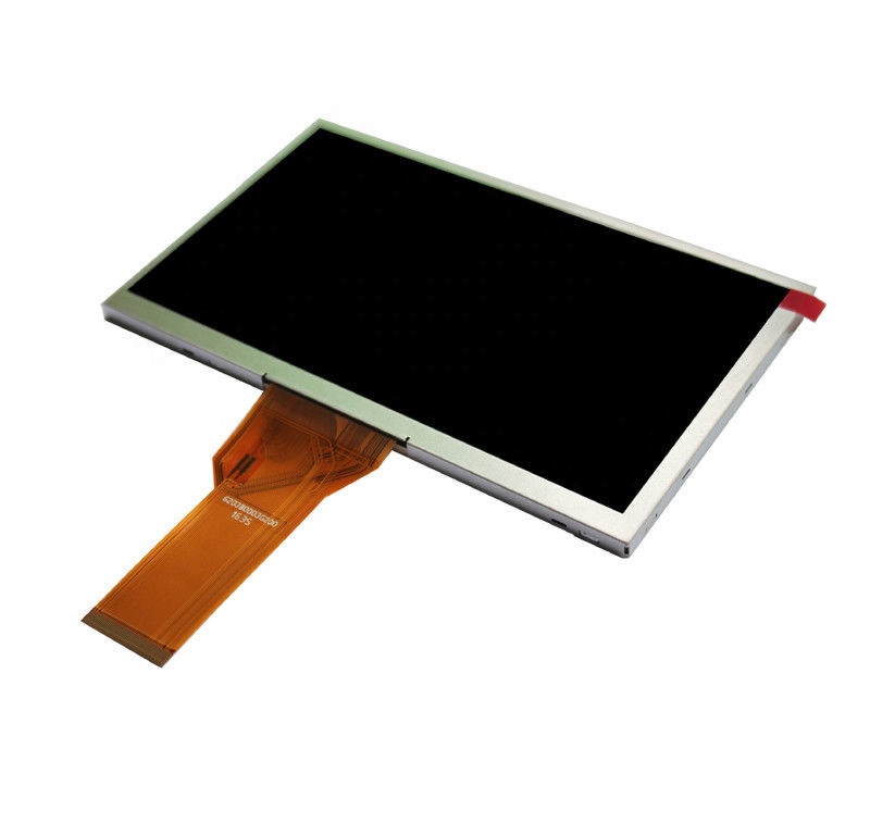
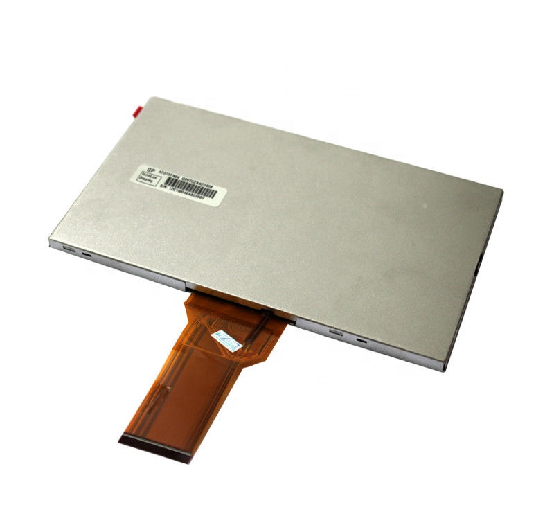
Innolux AT070TN94 7-inch RGB LCD | Ver.01 Specifications
AT070TN94 is a 7.0-inch, 800 × 480 a-Si TFT LCD module with parallel digital RGB input. The data below are checked against one identified manufacturer specification.
Display and mechanical specifications
| Parameter | Specification | Source pages |
|---|---|---|
| Model / manufacturer | AT070TN94 / Innolux Display Corporation | Cover; 1 |
| Diagonal / pixels | 7.0 inch; 800 × 480 pixels, RGB stripe (800 × 3 RGB subpixels × 480) | 1 |
| Display technology / mode | a-Si TFT active matrix; TN; normally white, transmissive | 1; 20 |
| Surface / view direction | Anti-glare; 6 o’clock reference viewing direction | 1; 20 |
| Active area, W × H | 154.08 × 85.92 mm | 1 |
| Module, W × H × D | 164.9 × 100.0 × 5.7 mm nominal; use mechanical drawing for tolerances and FPC geometry | 1; 20 |
| Dot pitch / pixel pitch | 0.0642 × 0.1790 mm / 0.1926 × 0.1790 mm (W × H) | 1; 20 |
| Mass | 154 g typical | 1 |
| Driver ICs / inversion | EK79713 source driver; EK73202 gate driver; 1+2 dot inversion | 1; 20 |
| Power consumption | Panel: 0.226 W typical; backlight: 1.674 W typical | 1 |
Parallel RGB interface and connector
The signal assignment provides 24 parallel RGB data inputs; Note 2 also specifies 18-bit RGB operation. It does not describe an LVDS input. Use the complete pin map and host timing for cable or controller selection.
| Item | Document-backed requirement | Source pages |
|---|---|---|
| Interface | 18/24-bit parallel digital RGB; 50-pin FPC, 0.5 mm pitch | 2–4; 20 |
| Recommended mating connector | Hirose FH12A-50S-0.5SH | 2; 20 |
| 18-bit input | Ground R0/R1, G0/G1 and B0/B1 (the two low bits of each channel) | 3, Note 2 |
| Clock edge | Latch data on the falling edge of DCLK | 3, Note 3 |
| DE mode | MODE=1; VS and HS high | 3, Note 1 |
| SYNC mode | MODE=0; DE grounded | 3, Note 1 |
| Reset / dithering | RESET active low; DITHB=1 disables and DITHB=0 enables internal dithering | 4 |
| Pins | Signals / function |
|---|---|
| 1–2 / 3–4 | LED+ anodes / LED− cathodes |
| 5 / 36 / 38 / 48 | GND |
| 6 / 46 | VCOM |
| 7 | DVDD |
| 8 / 9 / 10 / 11 | MODE / DE / VS / HS |
| 12–19 | B7 through B0 |
| 20–27 | G7 through G0 |
| 28–35 | R7 through R0 |
| 37 | DCLK |
| 39 / 40 | L/R / U/D scan controls |
| 41 / 42 / 43 | VGH / VGL / AVDD |
| 44 / 47 | RESET / DITHB |
| 45 / 49 / 50 | NC; no connection |
Pin summary: printed pages 2–4. Follow the full FPC drawing and scan-control definitions for connector orientation and board implementation.
Optical specifications
Specified optical conditions: DVDD=3.3 V, backlight current=180 mA and ambient temperature=25°C. Measurements are made in a dark room after 30 minutes of operation; see printed pages 14–17 for geometry and definitions.
| Parameter | Minimum | Typical | Maximum | Condition / reference |
|---|---|---|---|---|
| Luminance | 320 cd/m² | 400 cd/m² | Not specified | Center; pp.14–16 |
| Contrast ratio | 400:1 | 500:1 | Not specified | Normal direction; p.14 |
| Viewing, left / right / up / down | 60° / 60° / 40° / 60° | 70° / 70° / 50° / 70° | Not specified | CR ≥10; pp.14–15 |
| Response time, TON+TOFF | Not specified | 25 ms | 50 ms | White/black transitions; pp.14,16 |
| White chromaticity, Wx | 0.26 | 0.31 | 0.36 | CIE 1931; p.14 |
| White chromaticity, Wy | 0.28 | 0.33 | 0.38 | CIE 1931; p.14 |
| Luminance uniformity | 70% | 75% | Not specified | 9-point minimum/maximum; pp.14,17 |
Recommended operating electrical conditions
| Rail / signal | Minimum | Typical | Maximum | Source / condition |
|---|---|---|---|---|
| DVDD | 3.0 V | 3.3 V | 3.6 V | p.6; match host logic voltage |
| AVDD | 10.2 V | 10.4 V | 10.6 V | p.6 |
| VGH | 15.3 V | 16.0 V | 16.7 V | p.6 |
| VGL | −7.7 V | −7.0 V | −6.3 V | p.6 |
| VCOM | 2.6 V | 3.6 V reference | 4.6 V | p.6; optimize for each LCM |
| Logic high, VIH | 0.7 × DVDD | Not specified | DVDD | p.6 |
| Logic low, VIL | 0 V | Not specified | 0.3 × DVDD | p.6 |
| Driver current | Minimum | Typical | Maximum | Measurement rail |
|---|---|---|---|---|
| IGH | 0.05 mA | 0.2 mA | 1.0 mA | VGH=16.0 V |
| IGL | 0.05 mA | 0.2 mA | 1.0 mA | VGL=−7.0 V |
| IDVDD | 1 mA | 4.0 mA | 10 mA | DVDD=3.3 V |
| IAVDD | 5 mA | 20 mA | 50 mA | AVDD=10.4 V |
Current conditions: printed p.7. The module uses multiple supply rails; 3.3 V describes DVDD, not a complete single-supply module specification. Apply DVDD and VGL before VGH. Follow the complete power-on/off timing diagrams on pp.9–10.
LED backlight
| Parameter | Minimum | Typical | Maximum | Source / definition |
|---|---|---|---|---|
| Backlight voltage | 8.4 V | 9.3 V | 10.2 V | pp.7–8; at 25°C, 180 mA |
| Backlight current | 170 mA | 180 mA | 200 mA | p.7; whole backlight |
| LED life | 20,000 h | Not specified | Not specified | pp.7–8; minimum to 50% initial luminance at 25°C, 180 mA |
LED power is applied through pins 1–4. The 20,000-hour figure is a defined luminance-life value, not a warranty. Lifetime can decrease above 180 mA. Confirm the backlight-driver design for the actual assembly.
Timing reference
| Item | Specified reference | Source |
|---|---|---|
| Typical DCLK frequency | 33.3 MHz | p.12 |
| Frame rate | 60 ±5 Hz | p.12 |
| Horizontal active / typical total | 800 / 1056 DCLK | p.12 |
| Vertical active / typical total | 480 / 525 lines | p.12 |
Use the complete AC and input-timing requirements on pp.11–13. The document’s DCLK cycle-time and frequency endpoint tables do not fully correspond; confirm endpoint operating combinations with the manufacturer rather than deriving a new guaranteed range.
Absolute ratings and environmental qualification
The following limits are listed in the specification’s Absolute Maximum Ratings table (p.5). They are not substitutes for the recommended electrical settings above.
| Item | Minimum | Maximum |
|---|---|---|
| DVDD | −0.3 V | 5.0 V |
| AVDD | 6.5 V | 13.5 V |
| VGH | −0.3 V | 40.0 V |
| VGL | −20.0 V | 0.3 V |
| VGH−VGL | Not specified | 40.0 V |
| TOP, operation temperature | −30°C | 85°C |
| TST, storage temperature | −30°C | 85°C |
| LED forward current, each LED | Not specified | 25 mA |
| LED reverse voltage, each LED | Not specified | 1.2 V |
Reliability tests on p.18 include high-temperature operation at panel-surface temperature Ts=85°C for 240 hours, low-temperature operation at ambient Ta=−30°C for 240 hours, and operation at +60°C/90%RH for 240 hours. The 85°C condition is not an unconditional guarantee for ambient temperature or all optical performance in finished equipment.
The documented vibration test is 1.5G, 10–55–10 Hz, 2 hours per X/Y/Z direction; mechanical shock is 100G/6 ms. These component test conditions do not establish automotive certification, finished-system qualification or warranty coverage.
Packaging reference
| Item | Specification | Source |
|---|---|---|
| Quantity | 50 modules/carton, 2 rows × 25 | p.21 |
| Carton dimensions | 525 × 362 × 250 mm | p.21 |
| Total packed mass | 10.65 kg ±5% | p.21 |
Packaging is the reference configuration in this document. Confirm actual shipment packing, quantity and current commercial terms with the quotation.
Compatibility review and quotation
Send the complete panel label and revision, controller/cable information, required quantity, destination and application conditions. Compare the parallel RGB pin map, all power rails, backlight drive, timing and mechanical drawing before approving a substitute. Current production and stock status are confirmed separately from this 2023 specification.
Request AT070TN94 technical review and quotation
Frequently asked questions
What interface does AT070TN94 use?
The Ver.01 pin assignment identifies parallel digital RGB with R0-R7, G0-G7 and B0-B7 data, plus DCLK, HS, VS and DE. For 18-bit input, ground the two low bits of each color channel. The recommended connector is Hirose FH12A-50S-0.5SH.
What are the typical viewing angles?
At contrast ratio CR ≥10, typical left/right/up/down viewing angles are 70°/70°/50°/70°. The respective minimum values are 60°/60°/40°/60°, under the optical test conditions in the specification.
What does the 20,000-hour LED life figure mean?
It is the specified minimum time until luminance falls to 50% of its original value at ambient 25°C and backlight current 180 mA. It is not a product warranty; operating above 180 mA can reduce lifetime.
Does the specification confirm current supply or replacement compatibility?
Current production, stock, price and order terms must be confirmed separately. A replacement requires the complete model/revision, RGB pin map, power rails, backlight drive, timing and mechanical fit to be checked in the actual equipment.
Related engineering resources
AT070TN94 replacement guide · AT070TN83 V.1 comparison record · 7-inch size and interface selection · AT070TN83 replacement workflow · Industrial LCD buying guide · Industrial LCD interface comparison · Industrial HMI application requirements