Principle and structure of LCD TFT
Date:2019-04-26
Principle and structure of LCD TFT
Liquid crystal is a kind of substance which is not only like liquid (can flow) but also like crystal (has the optical properties of crystal). The arrangement of liquid crystal molecules has a certain order. Under the action of external electric field, the arrangement of liquid crystal molecules will change, which will affect its optical properties.
Liquid crystal display (LCD) is composed of two parallel thin glass plates. The distance between the two glass plates is very small, and the liquid crystal is filled with small units. The LCD panel itself does not emit light, it makes the LCD screen light up through the backlight of the LCD screen. The advantages of LCD are small size, light weight, large display area, stable picture, no radiation, low energy consumption and environmental protection. Compared with CRT, the power consumption of LCD is only 1 / 3 of that of CRT, the thickness is only 1 / 8, the weight is less than 1 / 3, and the space saving is more than 60%.
TFT LCD (thin film transistor), the abbreviation of thin film transistor, is the current top material LCD. It belongs to the active matrix type LCD. There is a special lamp on the back, which can "actively" control each independent pixel on the screen. This is also known as the active matrix TFT. It has fast response speed and large viewing angle, High color saturation. Because the arrangement of TFT LCD has memory, it will not recover immediately after the current disappears, which effectively improves the ability of playing dynamic pictures.
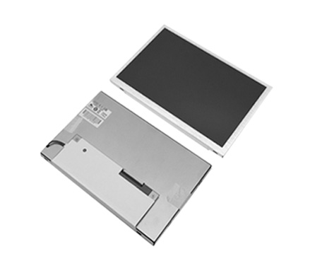
What is the did TFT LCD
The digital intelligence display TFT LCD is a special LCD. It is designed and produced according to the technical requirements of professional monitors applied in security, radio and television, medical, industrial and public media publishing, and is the fourth generation LCD product after Nb, PC and TV. With excellent display performance, it has been recognized as the most high-end and ideal LCD monitor display.
The characteristics of the did TFT LCD
1. High brightness
Compared with TV and PC LCD, the did LCD has higher brightness. TV or PC LCD screen brightness is generally only 250? The brightness of the LCD can reach 300-500 CD / m2 (< 20.1).
2. High contrast
The contrast of the did LCD is 1000:1 (< 20.1 ") and more than twice that of the traditional PC or TV LCD, which is three times of the general back projection.
3. Better color saturation
At present, the color saturation of ordinary LCD and CRT is only 72%, while the did LCD can reach 92% of the high color saturation. This is due to the color calibration technology developed for the did products. Through this technology, in addition to the color calibration of the still picture, it can also calibrate the color of the dynamic picture, so as to ensure the accuracy and stability of the screen output.
4. A wider perspective
PVA (patterned vertical alignment) technology is called "image vertical adjustment technology". With this technology, the visual angle can reach double 170 ° Above (horizontal and vertical).
5. Better reliability
The ordinary LCD is designed for TV and PC display, and it does not support continuous use for 24 hours. While the did LCD is designed as monitor and billboard, which supports continuous use day and night in public.
6. Plain display
LCD is the representative of flat panel display equipment, and it is a true flat display without distortion.
7. Ultra thin narrow edge design
The did products have the advantages of large display area, thin thickness and light weight, which can be easily spliced and installed. 40 "LCD panel splicing, its excellent narrow edge design, so that its single edge less than 1.2 cm, so that the edge effect will not affect the overall display of curtain wall.
8. Uniform brightness, stable and flickering image
Since each point of LCD keeps that color and brightness after receiving the signal, it does not need to refresh the bright spot as CRT. Therefore, LCD is uniform in brightness, high in quality and does not flash.
9. 120Hz frequency of frequency doubling refresh
The 120Hz frequency doubled LCD technology of did can effectively solve the drag and blur in the process of image fast motion, enhance the clarity and contrast of the image, make the picture clearer and the human eyes can not be tired for a long time.
10. Longer service life
The life of LCD LCD used by ordinary Nb, PC and TV is 10000-30000 hours, while the service life of back light source of did LCD LCD can reach 50000 hours. This ensures the consistency of brightness, contrast and chroma of each LCD screen used in splicing curtain wall after long-term use and ensures that the service life of curtain wall is not less than 50000 hours.
Characteristics of LCD mosaic wall
1. High definition, high brightness, high color range
Clarity, brightness and color saturation are three important performance indexes of liquid crystal.
2. Narrow edge design
Because the backlight tube is used as the light source, the edge of the LCD screen is generally wide, and the width of the edge distance of 46 inch ordinary LCD screen is more than 30mm. If used for splicing, the splicing gap shall be at least 60mm, which will affect the visual effect.
Therefore, the LCD splicing wall needs to be designed with a unique narrow edge structure, so that its edge is reduced by more than twice, so that splicing does not affect the visual effect. Table 1 is the description of splicing gap of splicing unit.
3. Splicing options
The splicing quantity of LCD splicing wall can be selected arbitrarily (line (m) × Column (n)), the screen size also has a variety of options to meet the needs of different use situations.
4. Flexible splicing display combination function
According to the requirements of different users, the personalized design can be carried out, and the functions of single screen display, whole screen display, any combination display, image roaming and image overlay can be selected.
5. Advanced screen parameters university function
Use liquid crystal for LCD splicing curtain wall
Hangzhou Xuhong Technology Co., Ltd. is a technology-based company of industrial color LCD module, industrial control display products and touch screen control. It is a professional supplier of industrial LCD drive solutions. It is an enterprise unit that carries out display and touch control of terminal equipment through LCD products and display drive solutions. Our long-term stable supply of 3.5 "- 32" industrial LCD screen, TFT LCD screen brand diversification, complete models, can meet different customers under different application environments, medical, vehicle special industry wide temperature, bright, wide angle Industrial LCD screen all stable supply.